Static Var Generator (SVG): A Guide to Next-Generation Reactive Power Compensation
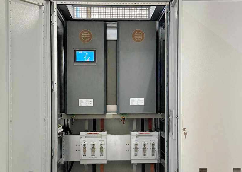
A Static Var Generator (SVG) is an active power electronics device that detects the grid’s reactive power demand within milliseconds and provides seamless compensation in both inductive and capacitive directions.
A Static Var Generator (SVG) is an active power electronics device that detects the grid’s reactive power demand within milliseconds and provides seamless compensation in both inductive and capacitive directions. Unlike traditional capacitor banks, the SVG behaves like a “current source” using an IGBT-based Voltage-Source Converter (VSC) architecture; it injects reactive current into the grid or draws it from the grid. This stabilizes the power factor (cos φ) at 0.99 or higher, prevents reactive energy penalties, and eliminates the risk of resonance. The response time is typically less than 15 ms; there is no need for step changes lasting seconds under dynamic loads. The SVG balances both the inductive motor loads of factories and the capacitive loads from data centers, UPS systems, and solar power plants within a single module. It has become the new-generation standard for reactive power compensation for facilities seeking to remain within EPDK limits, reduce transformer and cable losses, and protect sensitive automation systems. In this guide, we’ll walk you through what a Static Var Generator is, how it works, its differences from traditional compensation and STATCOM, its industrial applications, and how to choose the right solution for your facility, step by step.
If reactive power penalty charges are rising at your facility, compensation capacitors are failing frequently, and the power factor is fluctuating due to dynamic loads (VFDs, UPSs, injection molding machines, solar power plants), then you have reached the point where traditional multi-stage systems are no longer sufficient. In the sections below, we present an engineering-based approach to this problem.
Why Is Reactive Power Compensation Still Critical?
In electrical installations, devices that operate using magnetic fields—such as asynchronous motors, transformers, reactors, and induction furnaces—draw inductive reactive power (Q, kVAr) from the grid to create a magnetic field, in addition to the active power (P, kW) that drives the work process. Long cables, UPS systems, and data center power sources, on the other hand, can generate capacitive reactive power. Reactive power does not convert to active work; however, it increases line and transformer currents, raises losses, and disrupts voltage stability.
Compensation is the process of locally generating or balancing this reactive power at the point of consumption, rather than drawing it from the grid. The goal is not merely to avoid penalty charges on utility bills; it is also to use transformer capacity efficiently, reduce cable heating, and protect sensitive automation equipment.
Legal Limits and the Risk of Reactive Power Penalties in Turkey
According to EPDK and TEİAŞ regulations, the typical limits for customers with an installed capacity of 50 kVA or higher are as follows:
- Inductive reactive power limit: A maximum of 20% relative to active power consumption
- Capacitive reactive power limit: No more than 15% of active power consumption
- Target power factor: Generally between 0.95 and 1.00
If these limits are exceeded, a reactive energy charge will be applied to the bill. Distribution companies may also require corrective measures from facilities that degrade grid quality. In particular, facilities with solar power plants (GES) that experience increased capacitive loads at night and data centers with a high concentration of UPS systems often struggle to meet these limits using conventional “capacitive-only” compensation panels.
Changing Load Profiles in Modern Facilities
In traditional industries, loads changed relatively slowly. In today’s facilities, however, the situation is quite different:
- Dynamic inductive loads: Plastic injection molding, CNC machines, welding robots, cranes, and rolling mills generate peak reactive demand within milliseconds.
- Capacitive load: Data centers, medical imaging, online UPS systems, and solar power plant lines that do not operate at night lead to capacitive penalties.
- Harmonic distortion: VFDs, rectifiers, and switched-mode power supplies increase THD; conventional capacitors may resonate in this environment.
The result is an operational environment where slow-responding step-by-step panels cannot keep up, over- or under-compensation occurs frequently, and equipment lifespan is shortened. SVG technology was developed precisely to fill this gap.
What Is a Static Var Generator (SVG)?
A Static Var Generator (SVG), or “Statik Var Jeneratörü” in Turkish, is a fourth-generation active compensation device that uses high-speed semiconductor switches (IGBT or SiC modules) and Voltage-Sourced Converter (VSC) technology to instantly inject inductive or capacitive reactive current into the grid or draw it from the grid.
While conventional systems act as “reactive power reservoirs” using passive components such as capacitors and reactors, the SVG is a controlled current source. This distinction is critical in terms of response speed, bidirectional operation, and resonance safety.
The basic hardware components of the SVG are as follows:
- Power stage (inverter): A capacitor bank connected to the DC bus and a three-phase IGBT bridge
- Control unit (DSP): A digital signal processor that runs the real-time reactive power algorithm
- Measurement elements: External current transformers (CTs) connected to the load or grid side
- Linking reactor (L-filter): Current control between the inverter output and the common connection point (PCC)
How Does an SVG Work? Step-by-Step Mechanism
The SVG’s operating cycle is a closed-loop control cycle that repeats on the order of microseconds:
- Sensing: External CTs continuously sample the load current and line voltage.
- Calculation: The DSP calculates the phase angle, reactive power change, and the under/over reactive current at the fundamental frequency using the instantaneous reactive power algorithm.
- PWM Generation: The controller sends high-frequency pulse-width modulation (PWM) signals to the IGBT driver boards.
- Voltage/Current Injection: The IGBTs turn on and off to generate an AC voltage (Ui) at the inverter output, with precisely adjustable amplitude and phase.
- Reactive current direction:
- Ui = Us → No reactive current flow (balanced state)
- Ui < Us → The SVG draws inductive current from the grid (neutralizes excess capacitive power)
- Ui > Us → The SVG injects capacitive current into the grid (compensates for inductive load)
- Feedback: The grid-side CT transmits the compensation result to the DSP; a stable power factor is maintained through closed-loop control.
Thanks to this architecture, the response time is typically less than 15 ms, and the dynamic response occurs on the order of 50 µs. The difference is clear when compared to the step transitions of conventional contactor-based panels, which take seconds.
Comparison of a Conventional Capacitor Bank with an SVG
Conventional compensation (reactive power control relay + contactor/thyristor + capacitor stages + filter reactors) has been in use for decades. However, its technical limitations have become apparent in modern facilities with dynamic and capacitive loads.
Three key practical outcomes stand out:
In addition to total distortion, the dominant harmonic is also significant. For example:
· Stepless compensation: The cycle of over- or under-compensation is broken; the target PF remains constant.
· Bidirectional operation: The same device balances inductive motor loads during the day and capacitive UPS/PV system loads at night.
· Zero resonance: The risk of capacitor explosions and reactor overheating in environments with high harmonic content is eliminated.
These advantages are a common result of the IGBT-based VSC architecture. In new-generation SVGs using SiC modules, internal losses and cooling requirements are further reduced, taking efficiency and compactness to the next level.
Are SVG and STATCOM the Same Thing?
In the literature, the terms SVG (Static Var Generator) and STATCOM (Static Synchronous Compensator) are often used interchangeably. The physical topology is the same: both are voltage-sourced converters (VSCs) connected in parallel to the grid, with DC-bus capacitors and IGBT control. The difference lies in the application scale and industrial nomenclature.
In short: STATCOM is used at the transmission/distribution scale, while SVG is used at the facility/panel scale. SVG is the correct product class for factories, data centers, or commercial buildings.
Aha Teknoloji Varmatik SVG: Field-Focused Active Compensation
Aha Teknoloji’s Varmatik SVG series is a modular product that applies the active compensation principles summarized above to industrial panel applications. While many SVGs in the industry use classic silicon IGBTs, the Varmatik SVG is designed with a SiC (Silicon Carbide) module. The following specifications are based on catalog technical data; exact values for specific projects must be verified using the official technical data sheet.
The SiC Technology Advantage in Varmatik SVG
Unlike many products in the industry, Aha Teknoloji’s Varmatik SVG series uses SiC (Silicon Carbide) modules. Thanks to this new-generation semiconductor technology:
- Internal energy losses have been reduced by 45%
- The switching speed is higher than that of conventional IGBTs
- It features a more compact design and requires less cooling
- This translates to lower operating costs in the long term
Note: The statement in the catalog, “we have reduced power loss by up to 45%,” means that the device’s internal switching and conduction losses have been reduced compared to conventional silicon IGBTs; it is not a promise of a 45% savings on the facility’s total electricity bill. The practical result is increased device efficiency (typically ≥ 98.5%), reduced heat within the panel, and lower thermal stress on the semiconductors, leading to an extended service life and improved stability.
Modular Capacity and Compact Design
Single-module options are available in 33 kVAr, 100 kVAr, and 300 kVAr. As demand increases, capacity can be expanded by connecting modules in parallel; customizable cabinet outputs can scale to high kVAr levels. The SiC Module’s low-loss profile, combined with its compact cassette-type design, provides significant space and cooling savings compared to conventional passive panels and many conventional IGBT-based SVGs. Typical module dimensions are approximately 920 mm in height and 534 mm in depth; weights vary depending on the power class.
Performance Parameters (Summary)
- Semiconductor technology: SiC (Silicon Carbide) Module
- Nominal voltage: 400 V (350–415 V) or 690 V (480–790 V)
- Frequency: 50/60 Hz (operating range 45–65 Hz)
- Target power factor: −1.00 … +1.00, adjustable
- Response time: < 15 ms
- Dynamic response: < 50 µs
- Grid configuration: 3P3W or 3P4W
- Communication: RS485 (Modbus-RTU), Ethernet; HMI touchscreen
- Expected service life: Long operating life with metal-film DC busbar capacitors
- Additional function: Active phase balancing by reducing negative and zero-sequence currents
The Varmatik SVG can also be used in hybrid configurations in conjunction with an AHF (Active Harmonic Filter); this allows for the integration of reactive power and harmonic compensation within the same panel architecture.
Where Is SVG Used?
SVG is the ideal solution for any modern facility where reactive power fluctuates rapidly, where there is a risk of capacitive penalties, or where panel space is limited.
Commercial Infrastructure and Critical Buildings
· Data centers: Server PSUs and online UPSs generate capacitive reactive power; SVG prevents penalties with a response time of milliseconds.
· Hospitals: MRI, CT, and operating room loads cause sudden spikes; voltage fluctuations affect sensitive equipment.
· Malls, airports, and train stations: The dynamic reactive power demand from elevators, escalators, and HVAC systems is balanced.
Industrial Manufacturing
· Plastic injection molding and automotive: Press and spot-welding robots perform inductive engagement that changes within seconds; conventional relays cannot keep up.
· Textiles, food, cement: The risk of circuit breakers tripping and motor overheating is reduced in continuous production lines.
· Mining, oil and gas, crane systems: Voltage stability is ensured under heavy dynamic loads.
Renewable Energy (Solar / Wind)
In solar power plants, inverters generate active power during the day but stop production at night; due to transformer and cable capacitance, the facility may incur a capacitive penalty. A bidirectional SVG supports compliance with grid regulations by providing compensation in both directions, day and night.
How to Choose the Right SVG for Your Facility?
The correct SVG size and configuration are determined not by “selecting the largest module” from a catalog, but through engineering calculations based on measurements.
1. Perform a Power Quality Measurement
Collect at least one week of Class A-compliant power quality data. The recording must include:
- Trends for active power (P) and inductive/capacitive reactive power (Q)
- Time series of power factor (cos φ)
- THDi / THDv and dominant harmonics
- Phase imbalance percentages
- Peak kVAr demand (both inductive and capacitive)
2. Collect Infrastructure Parameters
· Transformer capacity (kVA), %Uk, primary/secondary voltage
· Main circuit breaker and current CT ratio/class
· Existing compensation panel (stage capacity, reactor ratio)
· Presence of a generator and compensation requirements when the generator is in operation
· Load types: VFD, UPS, welding equipment, solar power systems, etc.
3. Evaluate Physical and Environmental Conditions
· In-panel or wall-mounted installation area
· Ambient temperature and ventilation
· Altitude (derating at high altitudes)
· IP protection requirements (dusty/humid environments)
· SCADA/BMS communication infrastructure (Modbus / Ethernet)
4. Determine Capacity and Architecture
The kVAr capacity is selected by adding a safety margin to the measured peak reactive demand. In expanding facilities, modular parallel connection offers advantages. If harmonic levels are high, a hybrid SVG + AHF architecture is evaluated. The target PF, grid configuration (3P3W/3P4W), and voltage class (400 V / 690 V) are clarified. Semiconductor technology (classic IGBT or SiC module) should also be included in the selection criteria in terms of efficiency, cooling, and operating costs.
Conclusion: The Transition from Conventional Compensation to Active Control
The Static Var Generator (SVG) is a technology that shifts reactive power compensation from mechanical stages to real-time power electronics control. Thanks to its IGBT-based VSC architecture, it offers bidirectional operation, millisecond response times, a resonance-free design, and a stable power factor—providing a clear operational advantage over conventional panels for facilities with dynamic loads, such as factories, data centers, hospitals, and solar power plants.
Aha Teknoloji’s Varmatik SVG series adapts this transformation to field conditions with high efficiency provided by SiC modules, a modular architecture offering 33, 100, and 300 kVAr capacities, a response time of <15 ms, and active phase balancing capabilities. The first step toward the right solution is always measurement and engineering analysis.
Contact the Aha Teknoloji engineering team to determine whether your facility is suitable for the Varmatik SVG. We provide end-to-end support for power quality measurement, capacity calculation, and panel integration.
